The First Siren Project
Federal Thuderbolt 1000 Restoration
| Warning Sirens Main Page | Thunderbolt Restoration | Chopper/Rotator Restoration |
| Blower Restoration | Thunderbolt Control Panel | Some Thunderbolt Information |
Thunderbolt Siren RCM Control Panel
The Thunderbolt siren uses a fairly elaborate set of electro-mechanical controls for operation. Since the Thunderbolt has three seperate motors, blower, rotator and siren chopper, it uses what Federal Signal called an "RCM" cabinet with three motor starters (contactor relays) to operate it. The control relays are connected with a time delay relay to operate the Thunderbolt in a mode that results in the siren maintaining a high sound volume at all pitches of siren operation. This is all explained below. The Thunderbolt 1003 uses a second motor control panel called an RCM 3 in addition to the RCM panel. The RCM 3 only controlled the Hi-Lo solenoids for the 1003 siren. For siren signal timing on Federal Sirens the Federal AR, AF or PGA timers were used.
The first Thunderbolt I restored didn't have an RCM control panel with it when I got it so I used a panel that was salvaged from an early-mid 1970s model Thunderbolt. (shown below)
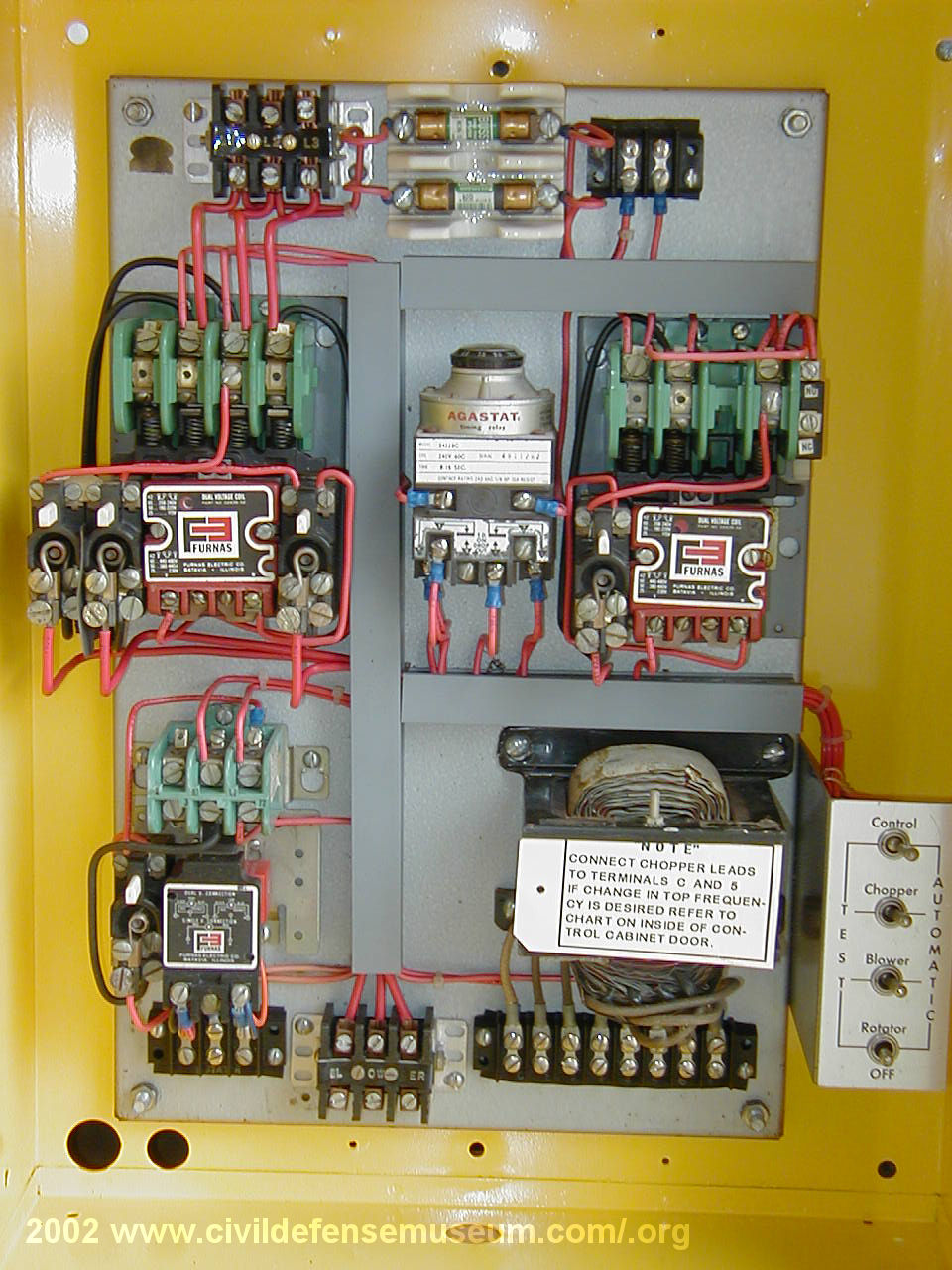
This is a Federal Signal RCM1A cabinet which is equipped with three motor starters (contactor relays). The 3 greenish colored components are the motor starter contacts. The starter activation coils are just below the contacts. These starters allow switching of the high current to the various siren motors by a lower current switching contol circuit. The silver and black "AGASTAT" component in the center of the panel is a time delay relay. This time delay relay keeps the rotator and blower motors activated while the chopper starter turns on and off during the attack (wavering) signal. The time delay is adjustable up to 15 seconds but when operating with one of the orignal Federal siren control timers setting the time delay with much difference With the blower activated during the up and down portion of the chopper cycle the sound output of the Thunderbolt is kept at a high volume during the entire cycle due to a constant high volume of air being forced through the siren chopper by the blower.
This was Federal's main design goal with the Thunderbolt; to keep the siren at full sound volume through the entire signal.
The large transformer at the lower right of the panel by the swiches controls the pitch of the chopper motor. This transformer has several voltage hook-ups (taps) which allows the top pitch of the siren to be set. (see below for more details)
The RCM1A is used with the Thunderbolt siren when the siren is operated from a 3 phase power source. The RCM1B is used with a single phase power source. This RCM1A is the control panel I restored for my Thunderbolt restoration. Earlier and later versions of the RCM control panel are very similar to this panel. The line input power connects to the large terminal block at the top left of the panel. The rotator connects to the bottom left small terminal strip, the blower connects to the large terminal block at the bottom center of the panel and the siren chopper connects to the terminal strip at the bottom right of the panel below the large transformer. I cover the different versions of the RCM panel on the Thunderbolt Information Page. Click image to see larger.
Chopper Pitch Control Transforer and Test Switch Panel
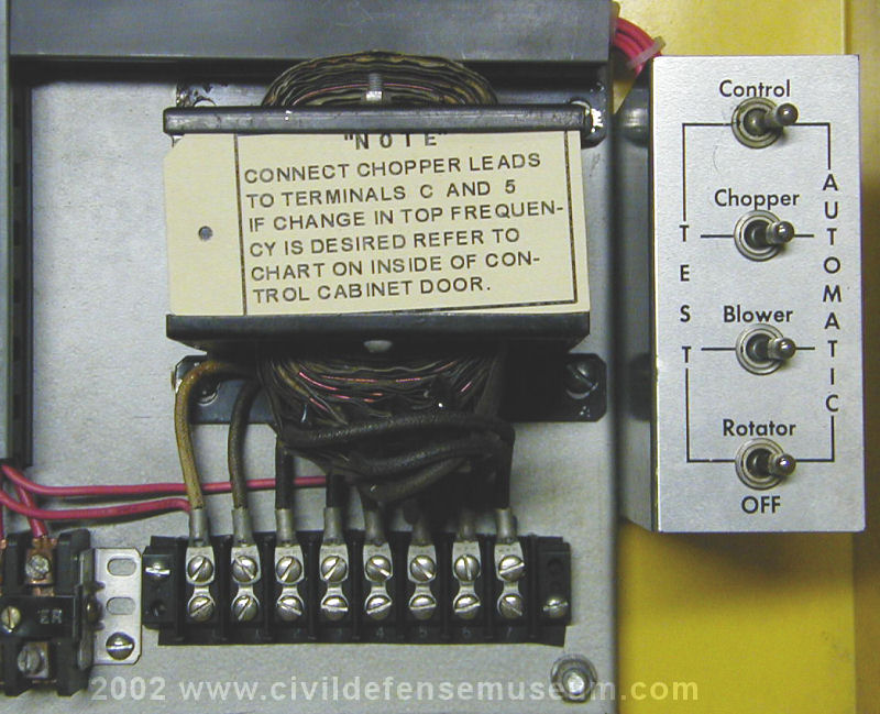
Here is a close-up of the siren chopper motor hook-up terminal strip, chopper auto-transformer and test switch panel. The most unique feature of the Thunderbolt siren is the ability to change the top sound pitch of the siren. This was done by connecting the siren chopper circuit to one of a series of output voltages at the chopper transformer terminal strip. On later RCM panels the terminals were labelled with the voltages at each terminal from 110 to 230 volts in 20 volt increments between terminals. The pitch of the siren can be changed by hooking up the siren chopper motor to one of the various terminal strip terminals. One wire of the chopper motor is connected to the far left (common) terminal. The pitch is lowest when the other wire to the chopper is hooked up to the terminal second from the left (110 volts) and the pitch is highest when the other chopper wire is hooked to the far right (230 volt) terminal.
The test switch panel at right in the photo allows each motor of the siren to be operated individually. Moving the respective switch to the test position manually activates that motor. When all the switches are at the Automatic position then the RCM panel is controlled by a switched signal (such as a siren control timer) connected to the "control" terminal strip at the upper right of the panel. Only the rotator motor can be turned to the OFF position.