The First Siren Project
Federal Thuderbolt 1000 Restoration
| Warning Sirens Main Page | Thunderbolt Restoration | Chopper/Rotator Restoration |
| Blower Restoration | Thunderbolt Control Panel | Some Thunderbolt Information |
Thunderbolt Siren Blower
The Thunderbolt siren uses a blower unit consisting of a roots blower and a large electric motor to pump 250 cubic feet of air per minute at 6.5 psi. through the chopper. This gives the siren it's high sound output by "supercharging" the siren chopper unit at the top of the pole. The blower of this first Thunderbolt I restored is a three phase A-series blower.
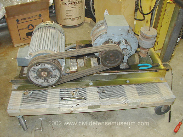
This photo shows the blower frame with the motor, on the left, and roots blower, on the right. Air is drawn into the top of the blower through the box shaped cover on top of the blower. The blower outlet air pipe comes out of the bottom of the blower and goes out in between the bottom blower frame rails at the right end of the unit.
The object with the series of stacked-up disks on top of the air pipe just to the right of the the blower is the blower pressure relief valve. This valve releases excess air pressure if the chopper is stopped, or if there is another obstruction of the air pipe which would result in closing off the air flow through the siren and out the horn. The stacked-disks are weights that sit stack on top of the valve to hold it down until the pressure exceeds 6.5 psi. When the pressure exceeds this amount the valve lifts up and releases the excess pressure while the blower is running. This way the blower is protected from overloading. Later blowers used differnt relief valve weights that set down around the relief valve itself instead of having them all stacked up on top of the valve.
This motor and blower are not the originals that were with this siren. The original roots blower was completely rusted inside so I replaced it with a newer type smaller blower I got from another siren. (See below) This motor and blower came from a mid-1970s vintage Thunderbolt. The motor is a 7.5 hp 3-phase motor that checked good when I had it tested at a motor shop. I mounted the blower skid on a set of heavy casters to make the siren easy to move around.
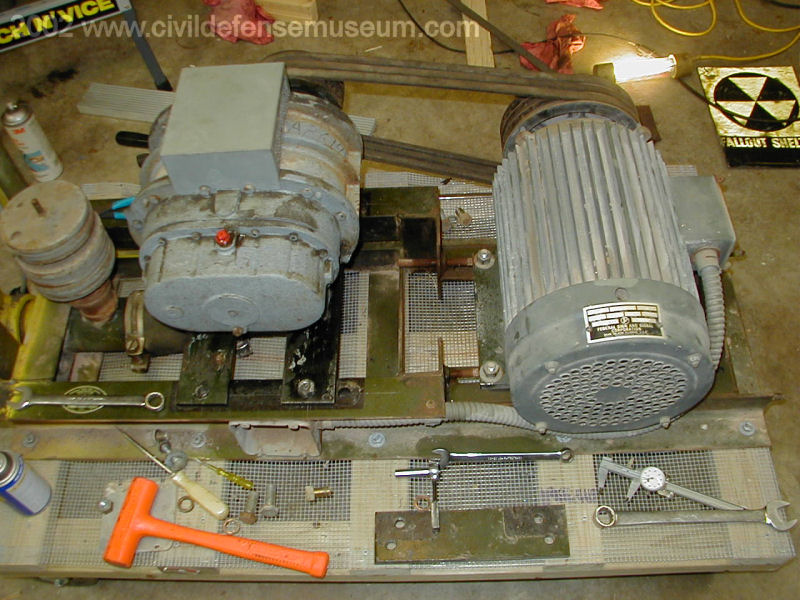
The above right photo shows the back side of the blower unit. You can see the air pipe and pressure relief valve to the left. I didn't repaint the blower frame. I just gave it a WD-40 and wipe down with a rag treatment. To see the other types of blowers that came with Thunderbolt sirens see the Thunderbolt Siren Information page.
The Original Roots Blower (Yes.. I'm an idiot or at least I was...)
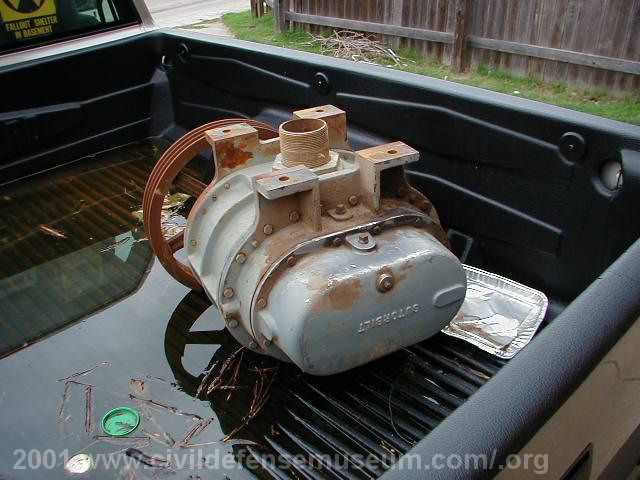
Here is the original Sutorbilt roots blower (I believe it's a 6M) that came with this siren. When I got the siren this blower was locked up due to water accumulating, for years, in the air pipe. I dumped this blower because I thought it was permantly locked-up and couldn't be saved. Well...knowing what I know now that was probably a stupid move because it most likely could have been worked free again without too much effort. I didn't know that at the time though so I replaced it with a later model Thunderbolt A series blower (4M) seen above. It would have at least been worth a try to work it loose.
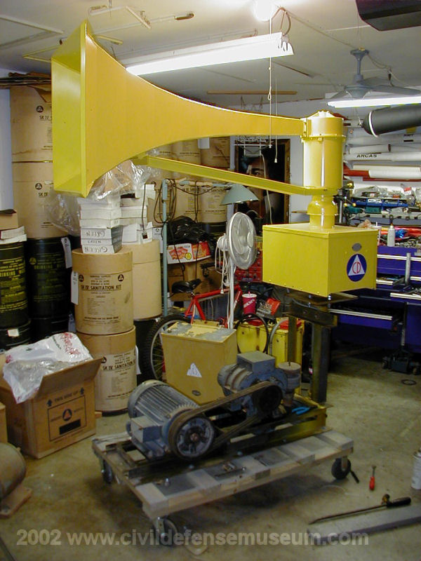
Here is the siren assembled, without the blower cover installed, sitting in my dump of a garage. The rotator can be operated in this arrangement because the weight of the blower and motor is more than enough to keep the thing from tipping as the horn rotates. This is how Thunderbolts were shipped from Federal. They were crated with the chopper/rotators attached to the blowers in this arrangement.