Civil Defense Museum - Virtual Shelter Tours
Old Dallas Civil Defense Emergency Operations Center
| Shelter Tours Main | Old Dallas EOC Main | Front Entry/Dormitory Room | Communications Room | Operations Room/RADEF Ops |
| Mayor's Office/Kitchen/Hallway | Mechanical Room | Air Filter System | Rear/Outside Entry |
Mechanical Room
 Click Photos To See Larger
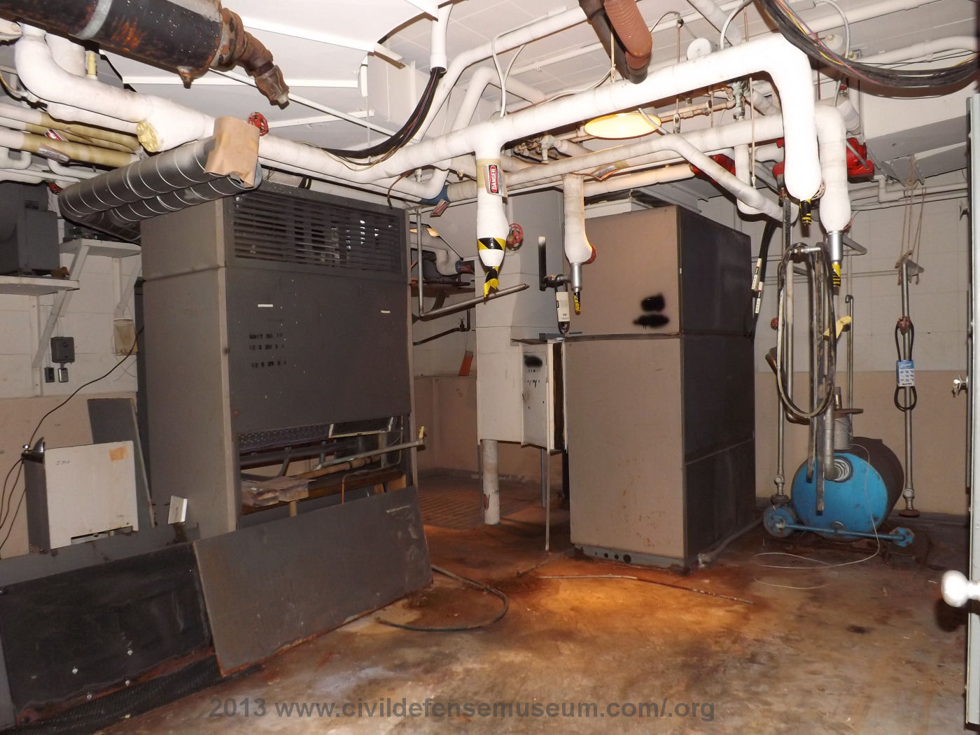
This photo of the mechanical room was taken looking into the room from the doorway. The doorway to the mechanical room is directly across the rear entry hallway from the men's restroom door.
The large gray/brown unit to the right in the picture is the shelter air system air conditioning unit. The air ducting from the air intake blowers leads into the back of this unit. The ducting out of the top of the unit goes out into the shelter space.
The large gray/brown unit at the right is the air conditioning unit for the mechanical room itself. It has an air outlet at the top and air filters in it but it has no ducting connecting it to the air system of the shelter area.There were originally two electrical generators in this room. The generators were located in front of the mechanical room air unit. I believe the four insulated pipes with the silver ends were the cooling water connections to the generators. The generator air intake pipes can be seen just to the left at the top of the mechanical room air unit. I don't know what the fuel source for the generators was. I can only assume it was diesel and that there must be an underground storage tank somewhere on the premisis but I have never thought to look for a fuel source when I have been there.
The silver round air supply ducts for the generators can be seen to the left of the unit in the center of the photo. These ducts lead back into an air duct which draws it's air from the air filter chamber.
The entry to the air filter chamber is in the far wall behind the center unit. The grating in the far corner, visible between the air conditioners, is the cover for the well pit.
The air filtering system is actually part of the mechanical/ventilation system of the shelter but I decided to give it a separate page due to it's somewhat complicated layout.
 |
 |
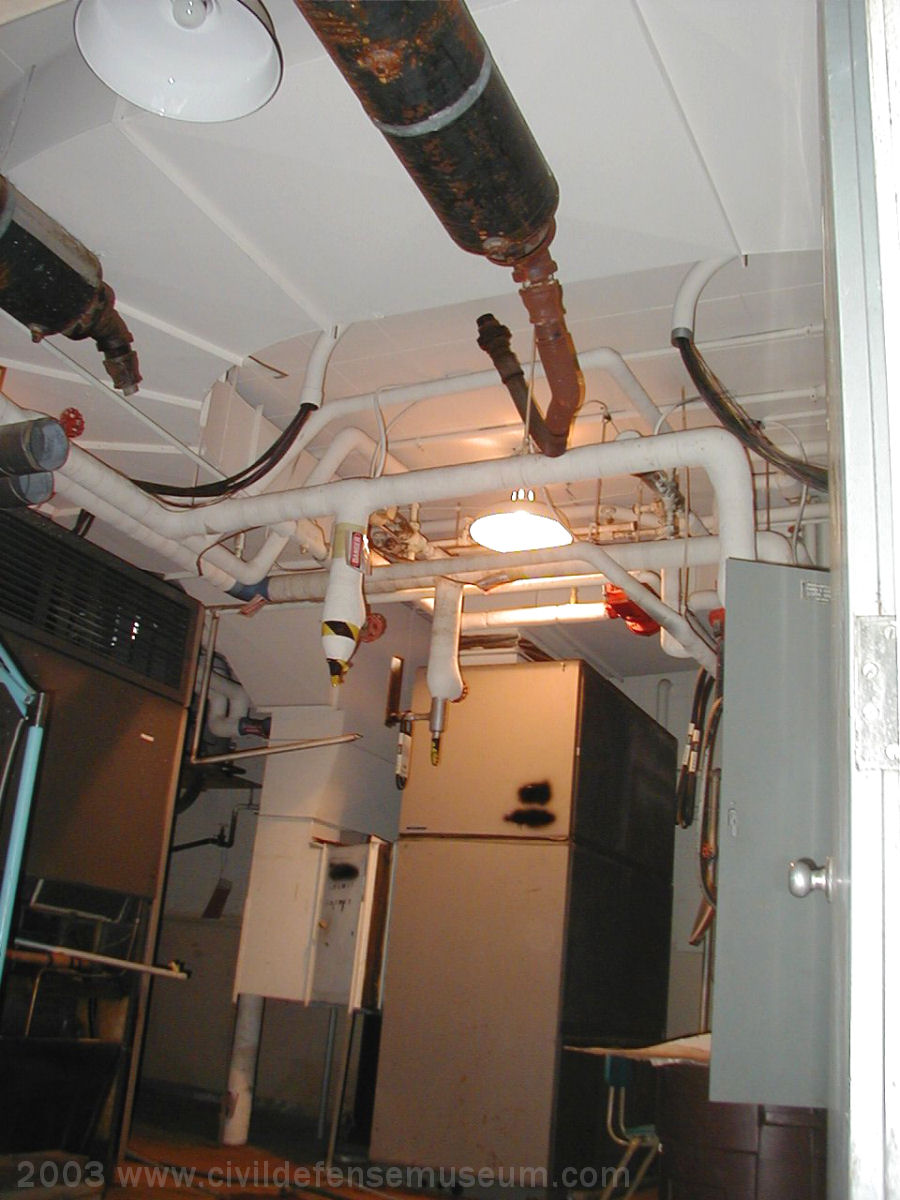
The above left photo photo was taken during the March 2003 visit. At the top center and top right under the large air duct are the generator exhaust pipes and mufflers. I believe this is a return air duct but now I can't remember looking to see how the air could be recirculated in the shelter. The generator power leads are hanging from their conduits and are draped up onto the water pipes just past the air duct.
I found out during the 2003 visit that the generators were removed some time in the 1990s. Another bit of new information I found out during the March 2003 visit is that the air conditioners cooled the air with well water instead of refrigerant. I don't how that worked because I think the well water would have to have been pumped through the air conditioners and then out somewhere to get rid of the heat. Not sure where the well water would have been pumped out to. When in heat mode I believe the hot generator cooling water would have been simply recirculated through the system for heating. I would really like to know how the entire system used to operate since I have an interest in all sorts of mechanical systems.
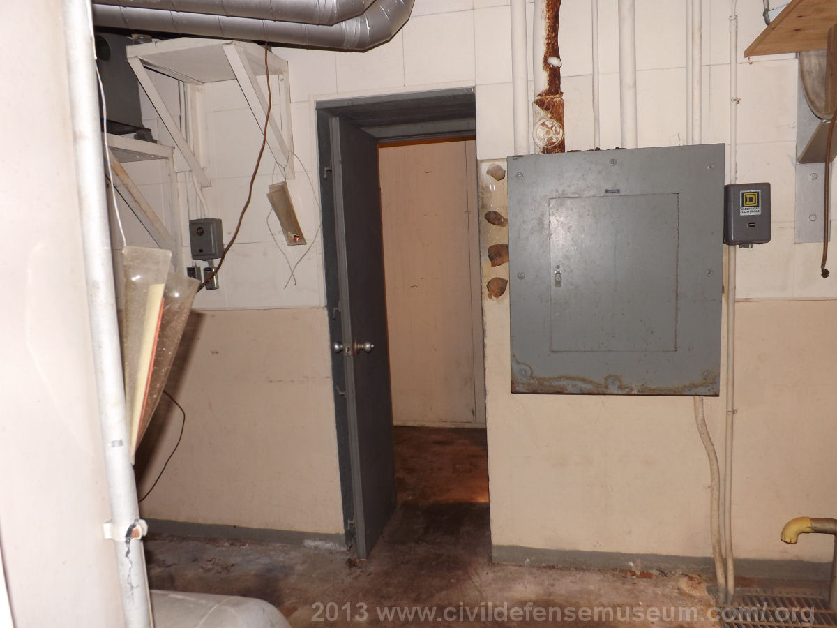
The above right photo shows the doorway at the back of the mechanical room that leads into the air filter/air intake chamber. The air intake blower brackets are just visible in the upper right of the photo. The generator air intake pipes are there just above the doorway going off to the left. For more a more detailed look at that system see the air filter system page.
Blast Door Hydraulic System
 |
 |
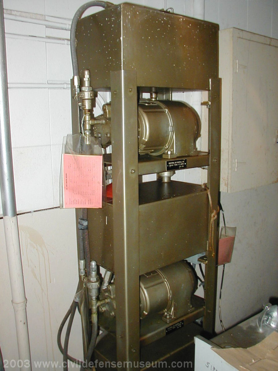
The above left photo shows the rack of hydraulic pumps and fluid tanks for the blast door lift cylinders. Each door has it's own independent system. During the 2013 visit the museum technician tried to open the exterior blast door. He turned on the hydraulic pump and shortly thereafter the pump shut down. We found that one of the breakers in the main panel had tripped and couldn't be reset. I believe that the problem was with the 50 year old breaker instead of the hydraulic motor. When we tried to reset the breaker it felt like something had failed mechanically inside the breaker. Needless to say I doubt if the city of Dallas will invest anything in trying to repair the thing.
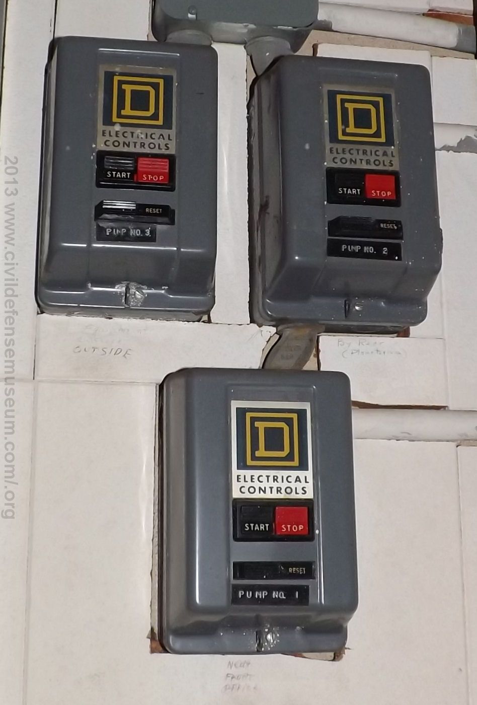
The above right photo shows the hydraulic pump manual motor starters. They are labeled PUMP NO 3 (top left),
PUMP 2 (top right) and PUMP NO 1 (bottom center).
Written in pencil on the wall tiles under the PUMP NO 3 starter is
"-illegible- Outside", under the PUMP NO 2 starter is "(By Rear) Planetarium" and under the PUMP NO 1
starter "Near Front Office"
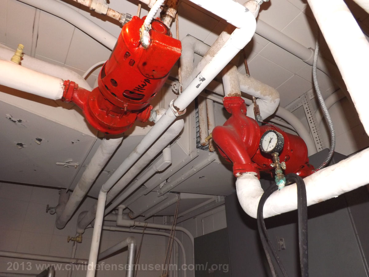
This photo was taken looking up from where the generators used to sit, towards the wall opposite the doorway into the mechanical room. The air ducting behind the two red pumps is the ducting leading into the shelter area. Just visible in the near duct is a set of coils just above to the left of the right red pump. I'm guessing these coils were used for heating with generator cooling water. I really want to go back now and try to figure out how all this used to operate!
Go To The Air Filter System |
Go Back To The Mayor's Office/Kitchen/Hallway |
Back to EOC Main |