Civil Defense Museum - Virtual Shelter Tours
Old Dallas Civil Defense Emergency Operations Center
| Shelter Tours Main | Old Dallas EOC Main | Front Entry/Dormitory Room | Communications Room | Operations Room/RADEF Ops |
| Mayor's Office/Kitchen/Hallway | Mechanical Room | Air Filter System | Rear/Outside Entry |
Shelter Air Filtering System
As someone with a mechanical background, I find the air filtering system in the Old Dallas EOC absolutely fascinating. Yes, I'll admit right now I got a bit carried away with this air filter business on this page. After I put everything together I thought to myself "how many people will even be interested in this?" Anyway here it is...
On this page I try to show the layout and provide speculative operation diagrams of the air filter system. It was very difficult to get good overall photos in the cramped confines of this area so I have included floor plans and speculative air flow plans of the filter system to, hopefully, make the description easier to understand. I have decided to call the two sections that make up the system the "Air Filter System" and the" Gas-Particulate Filter System". Click all images and plans to see larger.
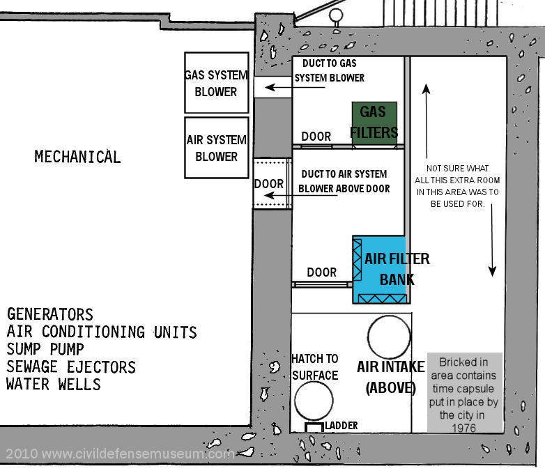
The Old Dallas EOC shelter has an air filtering system that consists of two sections. There is a large bank of air filters for filtering out larger fallout particles and there is also a pair of Gas Particulate filters as well. The system has two blowers to pull air through the filters and direct it into the shelter. The blowers then feed the air into the air conditioners for the shelter. The air is then fed through the air system into the shelter and then out the exhaust system at the back of the shelter. The air exhaust system blower is located in the Men's Restroom. I saw no evidence of any type of filtering in the exhaust system. The air is then fed out through the exhaust anti-blast valve on the surface.
New information October 2011.I found out in October of 2011, thanks to Matt Garret of Richardson Emergnency Management, that the bricked-in area in the corner of the air system intake chamber is a time capsule put in place by the City of Dallas. The time capsule is marked with a plaque located on the cinder block wall facing the escape hatch. I couldn't see it when I was there during previous visits because of all the old files and junk piled against the wall. Mr. Garrett also used to work with Dallas E.M. Thanks Matt for the information!
Here is my attempt at a "walk-though" of the air system. Hopefully it's not to confusing.Click all photos to see larger.
Air Intake Anti-Blast Valve and Air System Intake Chamber
(Starting with where the outside air enters the shelter) 1 |
 2 |
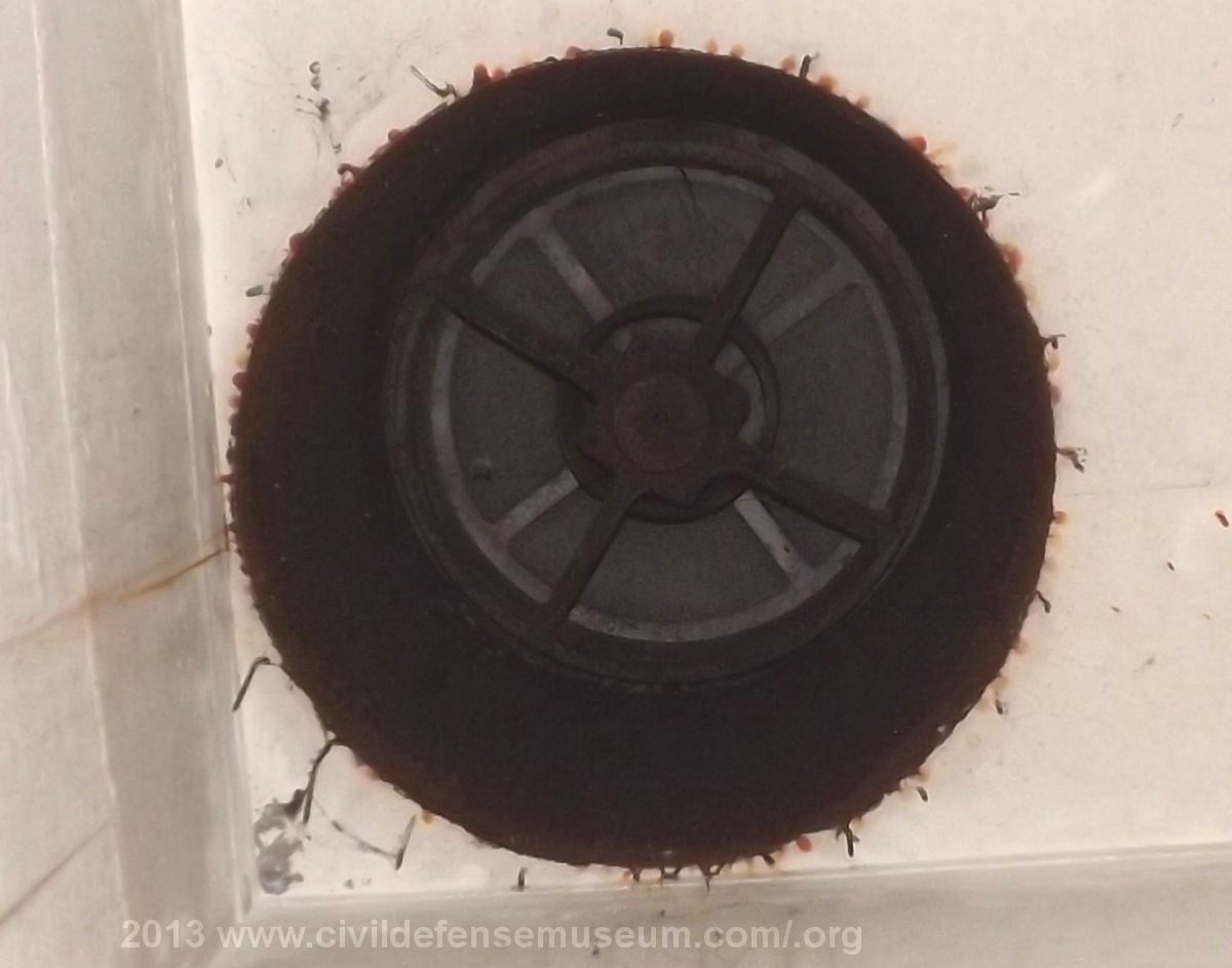
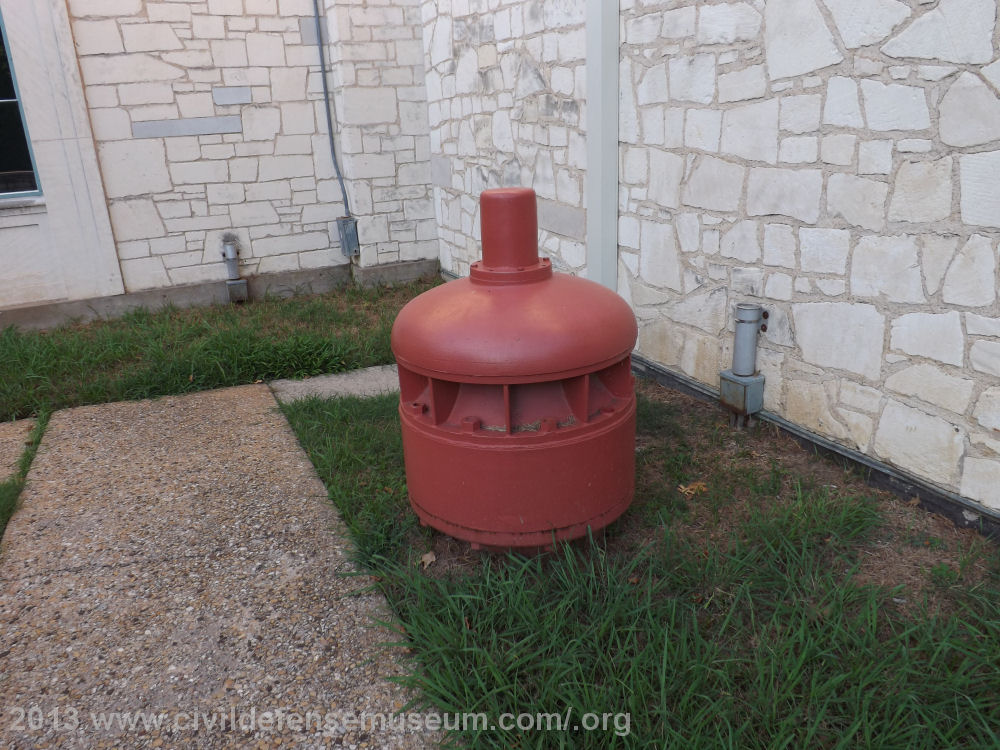
The above left photo - 1 shows the air intake "anti-blast" valve on the surface. The purpose of the anti-blast valve was to close and seal the shelter from the increase in pressure from a nuclear blast passing over. The valve would then open again when the outside pressure returned to normal. There is also an anti-blast valve on the exhaust air outlet (pictured here) for the shelter as well. For more information on the anti-blast valves see below.
The above right photo - 2 was taken from below the air intake anti-blast valve, inside the air intake chamber, inside the shelter. The valve appears to have an aluminum valve (lighter gray disk up inside the housing) held up by a large spring. The object that looks like a ring around the center cross of of the bottom bracket of the housing is the bottom of the spring. A sudden large increase in outside air pressure pushes this disk down against the spring pressure, closing the valve. It would be interesting to find out what the specs are on this valve to see how much pressure would close it.
Interesting Information About The Anti-Blast Valves Find the documents from the Dallas Municipal Archives here.
 3 |
 4 |
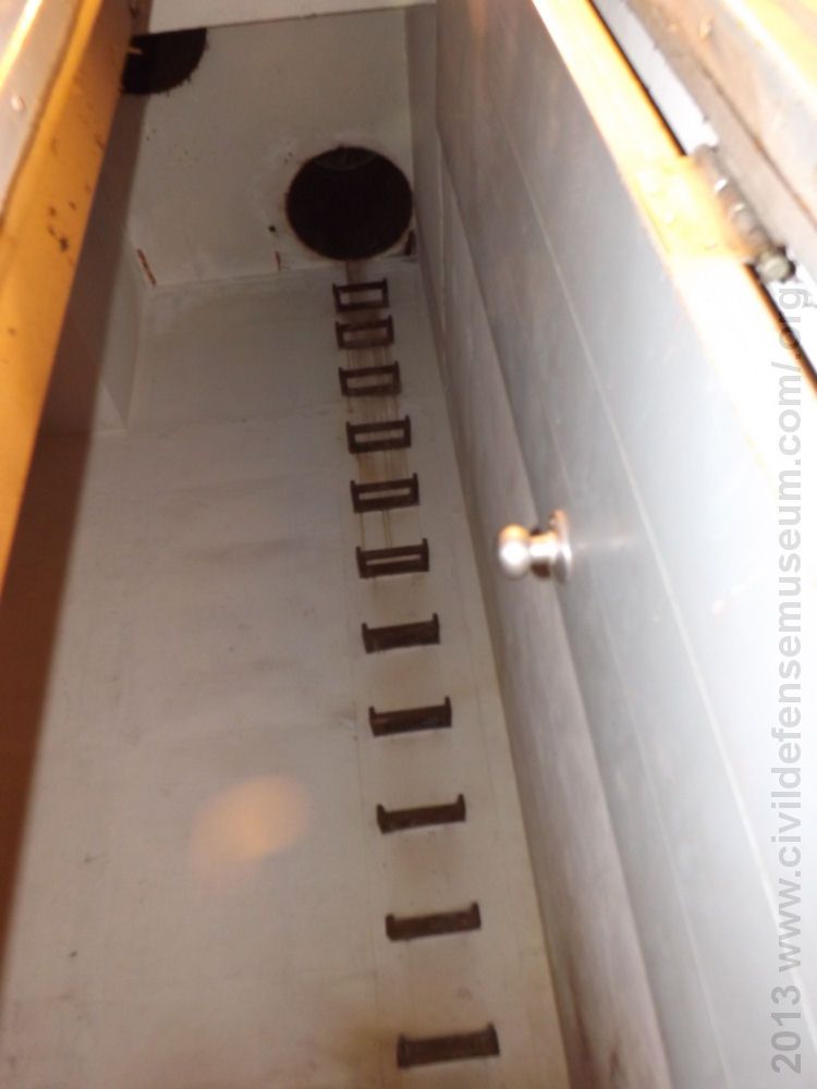
The above left photo - 3 shows the air system chamber looking up at the air intake with the underside of the anti-blast valve (visible at the upper left corner of photo) and the ladder up to the escape hatch manhole cover. The door that closes the intake chamber off from the rest of the filtering system is visible at the right of the photo. Closing this door causes the air to be drawn through the first set of filters. With the door open the air would simply pass trough the open doorway. Area designated as "Air Filter Bank" on the air system floor plan at top of page is to the immediate left in this photo.
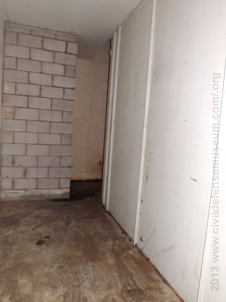
The above right photo - 4 was taken from the back of the large empty space in the air system chamber. To get an idea where this photo was taken from see the air system floor plan at the top of the page. I am standing in the area marked "not sure what all this extra room was to be used for" and I was looking back towards the area where the anti-blast valve and escape hatch ladder are located. The cinder block wall at left encloses the time capsule shown on the floor plan above. The white metal wall on the right is the divider down the middle of the air system chamber. The escape hatch ladder and anti-blast valve are just to the right of the opening between the cinder block wall and metal divider wall. Just on the other side of the metal wall divider is where the gas system filter chamber is located. I don't know why there was this much space left open in this area. Maybe there was a change in design of the air system after the concrete work was started? Just guessing. When I visited the shelter previously this area was full of junk. The shelter had been cleaned out completely so I was able to get this photo during my 2013 visit.
Air Intake Chamber And Air Filter Section / Air Filter Bank Primary Filters
 5 |
 6 |
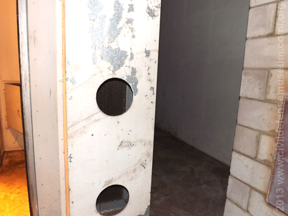
The above left photo - 5 was taken just below the air intake anti-blast valve, looking back towards the opening between the blocked-in time capsule enclosure and the metal divider wall seen in photo - 4 above. The metal panel with the circular holes covers the first set of air intake filters labeled as the Air Filter Bank in the filter diagram at the top of this page . The filters can be seen through the circular openings. This is the first set of filters that air passes though coming into the shelter. If I remember correctly there is another circular opening out of the top of the frame of the photo above. I believe the design intent of this panel with the circular openings was to reduce the intake of larger particulates into the first set of filters. (I believe that this panel opens to allow removal of the filters or maybe they are removed from behind.) The heavier particulates drawn into the chamber though the air intake anti-blast valve would drop and settle on the floor while any lighter particulates would be caught by this first set of filters. The second set of filters is just past the door opening on the left of this photo.
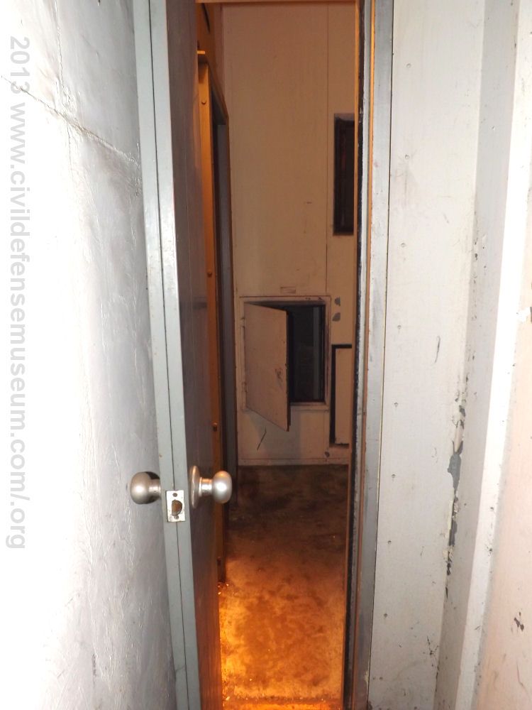
The above right photo - 6 was taken looking through the door next to the air filter bank seen in the floor plan (light blue) at the top of this page. The air intake anti-blast valve is above the camera and the escape hatch is above and behind me in this photo. The small gas filter chamber is straight ahead through that little half-open hatch in the far metal wall. The door to the mechanical room is between the near open door on the left and the hatch to the gas filter chamber. The door on the near left is the same door as seen on the right in photo - 3 above.
Air Filter Bank / Secondary Air Filters
 7 |
 8 |
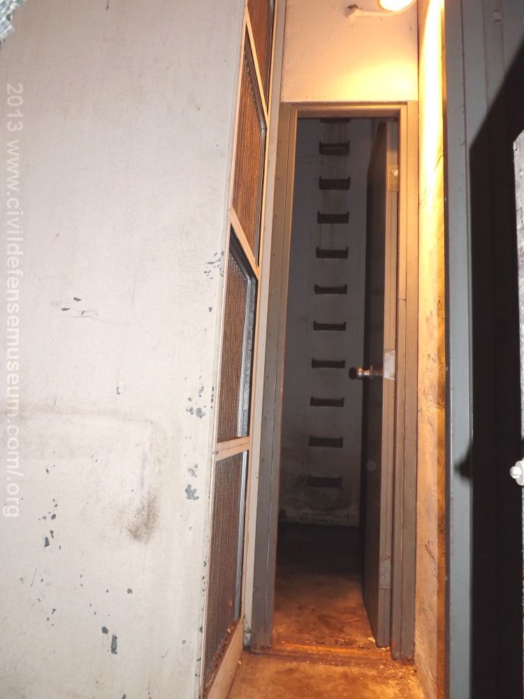
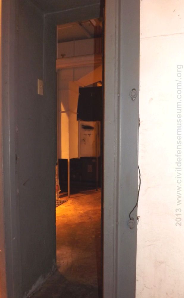
The above left photo - 7 was taken looking back into the air intake chamber from just in front of the small hatch to the gas filter chamber seen in photo - 6. The secondary air filters of the air filter bank can be seen at the center left of the photo. The ladder leading up to the escape hatch is there straight ahead on the far wall. The gray door jamb/opening visible on the immediate right is the doorway to the mechanical room.
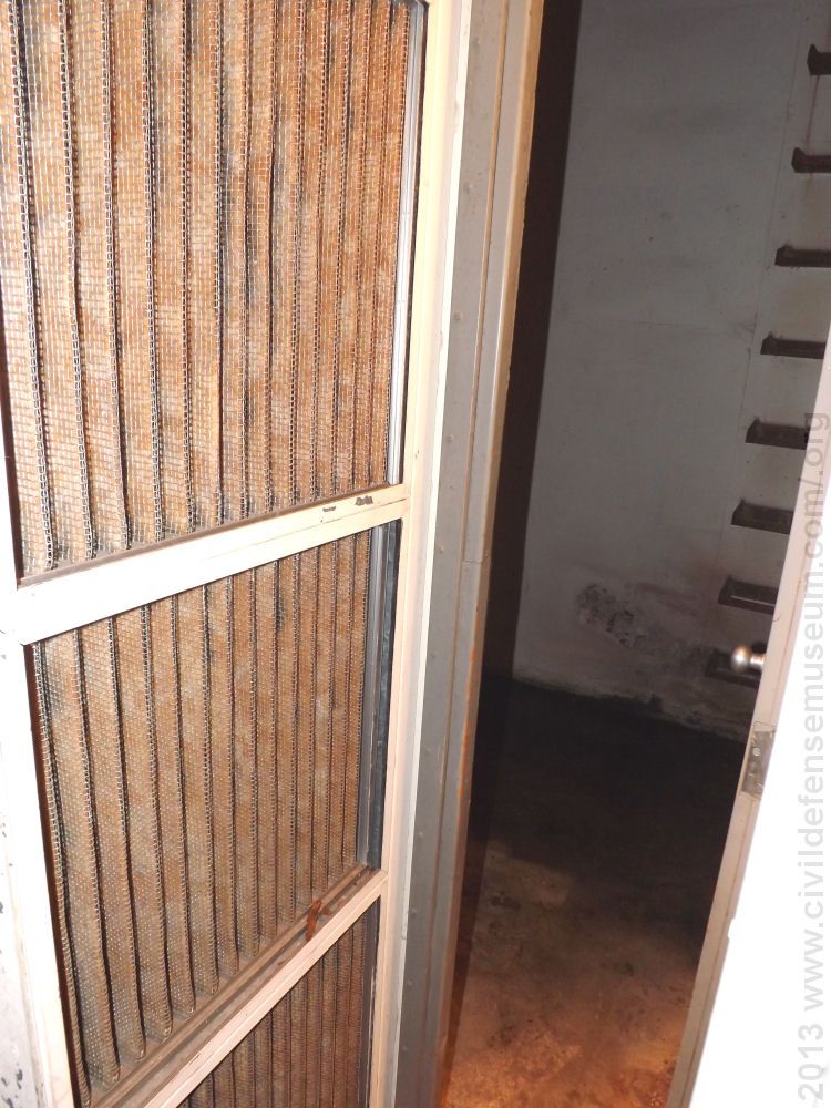
The above right photo - 8 shows a closer view of the secondary air filters of the air filter bank. This photo was taken with me standing in the doorway leading from the mechanical room into the air filter system. I was standing in the same doorway seen at the immediate right in photo - 7. There are four of the secondary air filters which are about 24 inches square.
 9 |
The above photo - 9 is mainly for orientation. This is looking back into the mechanical room from the viewpoint next to the gas filter inlets and the gas filter system chamber hatch which are to the immediate right. Notice the wall thickness through the doorway. Guesstimating it's approximately two feet of concrete.
I'll move on to the gas filter chamber after showing how the air enters the first blower system from the air filter system area.Blower Inlet Duct From Air Filter System Room And Feed Into Mechanical Room And Shelter Air System
 10 |
 11 |
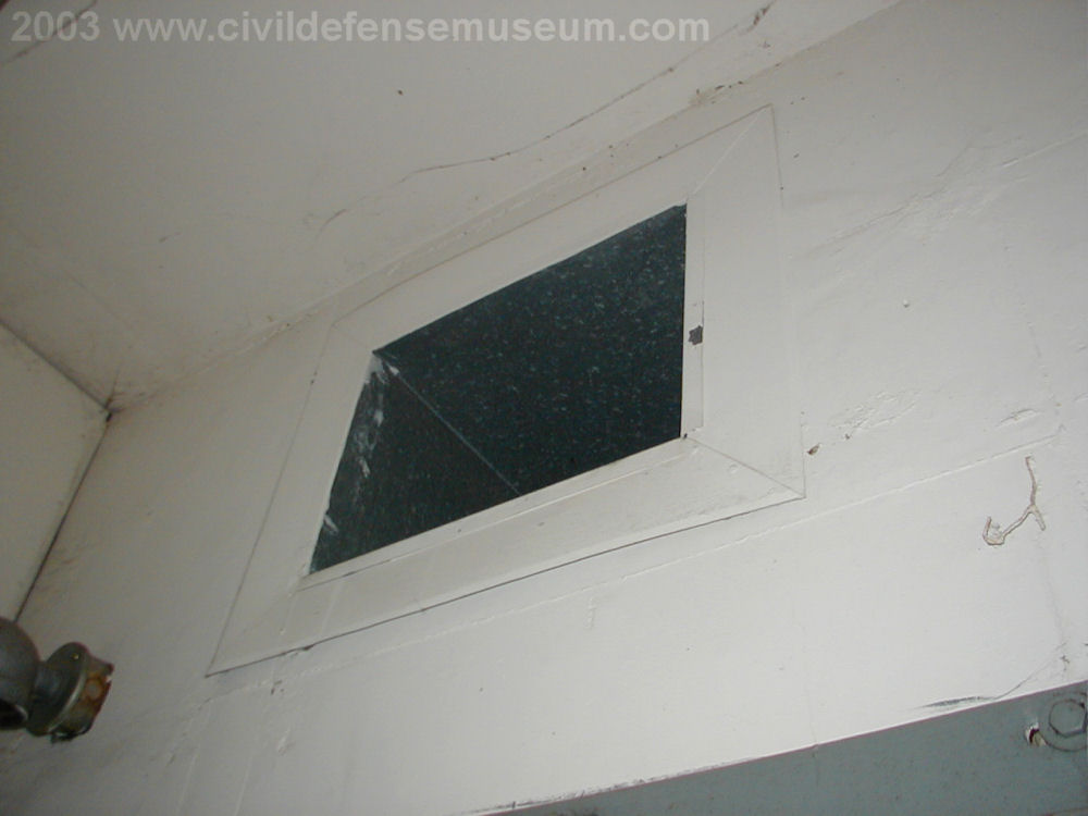
The above left photo - 10 was taken from the same position as photo - 9 but looking upwards to just above the doorway. The opening in the wall above the door is the (what I call) air system inlet duct. This is where the air that has been filtered through the air filter bank is drawn into (what I call) the air system blower. The gray frame of the door to the mechanical room is visible at the bottom right of the photo. This duct extends a few feet into the mechanical room (seen in photo - 11) where it attaches to the inlet of the air system blower. The generators also drew their intake air from the air system inlet duct.
The above right photo - 11 shows air system inlet duct seen in photo - 10 from the other side of the wall in the mechanical room. The gray top of the door to the air filter system room can be seen at the right lower corner of the photo. The small shelf on the wall next to the door is the mount for the air system blower. With this blower operating air could only be drawn through the air filter bank filters and delivered to the air conditioning system. The round silver air ducts were the ducts that supplied air to the generators in the mechanical room. Notice these ducts aren't on the outlet side of the blower but on the inlet side. The gray blower housing can barely be seen just past and between the two silver generator ducts. The outlet duct for the air system blower is the duct coming out immediately behind the air system inlet duct.
Now back to the next section of the filtering system with what I refer to as the "Gas System."
Gas - Particulate Air Filter Section
During my 2013 visit I was able to get much better pictures and actually get into the gas filter chamber because the shelter had been completely cleaned out. I learned something new when I entered the gas filter chamber....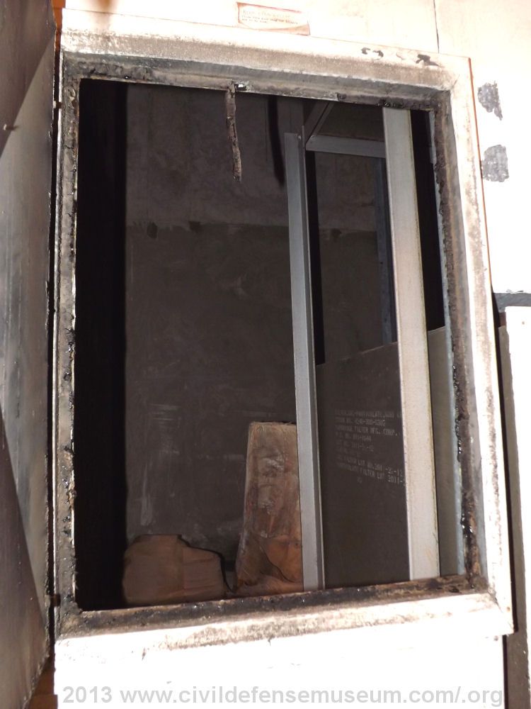 12 |
 13 |
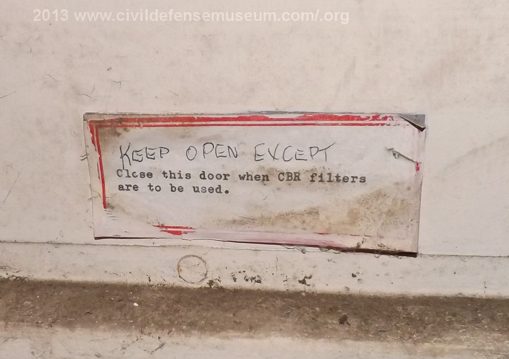
The above left photo - 12 was taken looking into the gas - particulate filter chamber hatch. I took this photo just next to the doorway leading in from the mechanical room. This hatch is the same hatch seen in photo - 6 above. Visible just through the hatch to the right is the olive-drab-green lower Gas - Particulate filter box. There are two of these filters in the chamber mounted on a metal rack. The air inlet to both filters come through square holes in the metal wall next to the hatch. The inlet to the lower filter has a metal cover over it which is right next to the hatch door frame there on the right edge of the photo.
The above right photo - 13 shows this small paper label which is located just above the gas -
particulate filter chamber hatch. The paper label says "KEEP OPEN EXCEPT Close this door
when CBR filters are to be used." In my two previous visits I had never noticed this little label.
Closing this hatch would draw the air through the gas - particulate filters only when the
gas system blower is running.
With the hatch open air would pass through the hatch opening and bypass the filters, through the gas filter chamber and into
the gas sytem blower if that blower is running.
Gas - Particulate Filter Inlet And Moving Into The Gas Filter Chamber
 14 |
 15 |
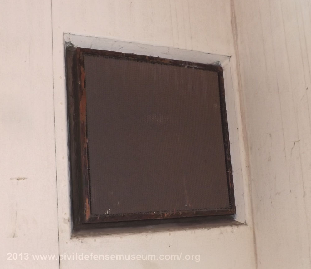
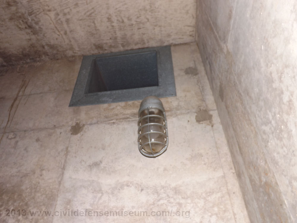
The above left photo - 14 shows the air inlet of the upper Gas - Particulate Filter. This inlet is just above and to the right of the hatch into the gas filter chamber seen in the above photo - 6. There is a very fine mesh screen covering the inlet of the filter.
The above right photo - 15 was taken looking into the gas filter chamber. The lower gas - particulate filter box is to the immediate lower right in the photo. The bottom and side of the upper gas - particulate filter can be seen (at the uppper right of the photo) attached to the top of the metal rack. Up in the very top corner of the room, near the ceiling and the vapor-proof light fixture, the gas filter system blower air inlet duct is just barely visible. This duct passes through the wall to the (what I call) the gas system blower.
Inside The Gas - Particulate Filter Chamber And Gas - Particulate Filters
 16 |
 17 |
The above left photo - 16 shows the upper gas - particulate filter box. The inlet end of the
box is sealed to the metal wall. The lower filter is mounted the same way. Since I wasn't able to
get into this room on previous visits I didn't know that the back covers were still on the gas filter boxes.
The back box covers evidently cover the filter outlets.
Another thing of note is that the filters appear to have been installed
permanently into the wall so I guess they weren't planning on replacing them as they were used.
The galvanized metal divider wall on the left in the photo is the same wall
that divides the center of the filter system chamber. On the opposite side of the galvanized divider
wall is were I was standing with I took photo - 4
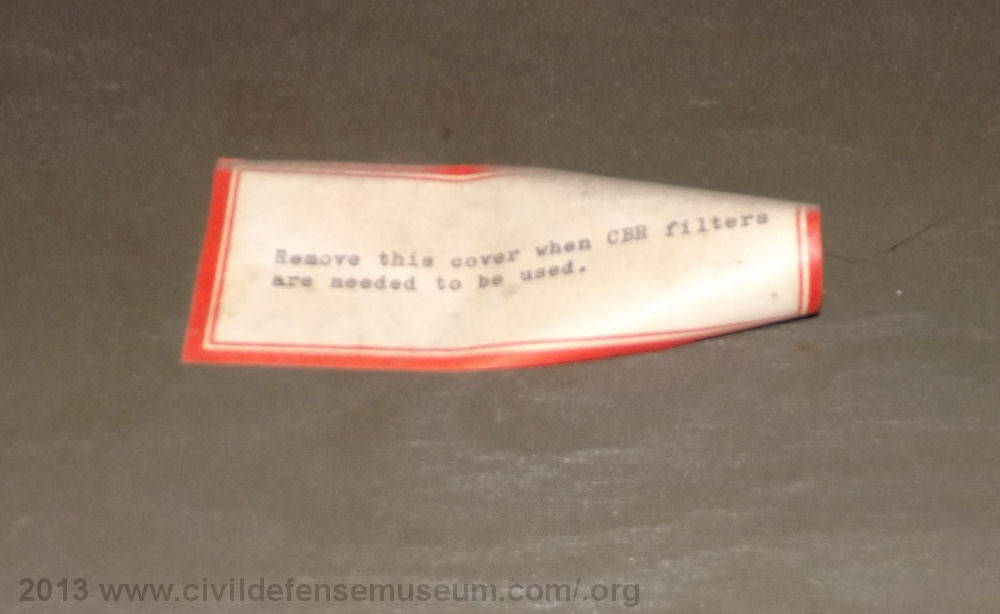
The above right photo - 17 shows the small paper label attached to the top gas - particulate filter box outlet cover. This photo is blurry but the label says "Remove this cover when CBR filters are to be used." CBR stands for Chemical Biological Radiological. The bottom filter box has the same cover and paper label on it also.
Gas - Particulate Filter And Gas Section Air Blower Inlet Duct
 18 |
 19 |
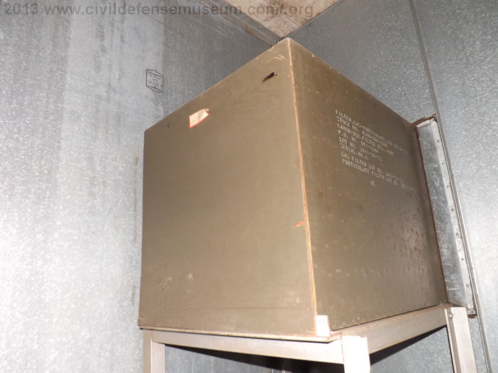
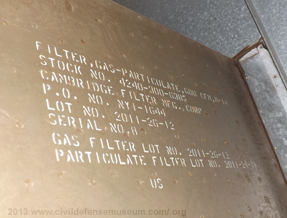
The above left photo - 18 shows the top filter box side identification label. Filter label reads as follows...
FILTER, GAS - PARTICULATE, 600 CFM, M14
STOCK NO. 4240-300-6385
CAMBRIDGE FILTER MFG. CORP
P.O. NO. NY1-1644
LOT NO. 2011-26-12
SERIAL NO. 8
GAS FILTER LOT NO. 2011-26-12
PARTICULATE FILTER LOT NO. 2011-24-11
US
Notice that, according to the last two lines of the label, that there are actually two different
types of filters in this assembly which is an M14 filter
assembly. There is the Gas filter and the Particulate filter. I actually found the military spec. for
the M14 filter. The specification number is MIL-F-50051 dated 29 June 1959. The spec. says that "not
more than one lot of C22 600 c.f.mm gas filters and one lot of C18 600 c.f.m. particulate filters shall
be represented in any one lot of M14 filters." (MIL-F-50051)
Evidently these M14 600 CFM Filters consist of one C22 gas filter and one C18 particulate filter.
The scope of the MIL-F-50051 spec. says in section 1.1 of the scope that "1.1 This specification
covers a gas and particulate filter for use in removing toxic gases and aerosols from the air forced or
drawn through the filter."(MIL-F-50015) To see the MIL-F-50051 spec. click here for the PDF file.
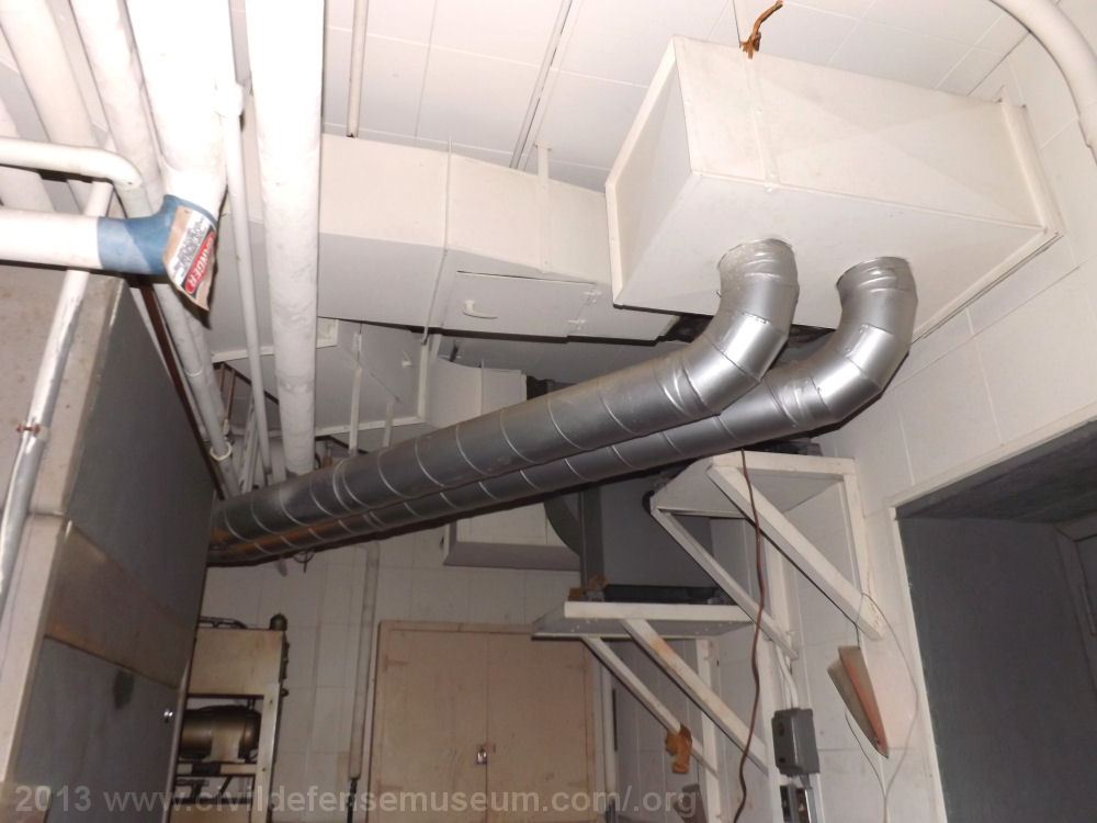
The above right photo - 19 shows the air inlet duct that leads to the gas system blower from the gas filter chamber. This duct passes through the concrete wall just like the air filter system blower inlet duct seen in photo - 10 into the mechanical room where it attaches to the gas sytem blower. Seen in photo - 20.
Gas System Duct & Blower / Another View Of The Filter Section Duct
 20 |
 21 |
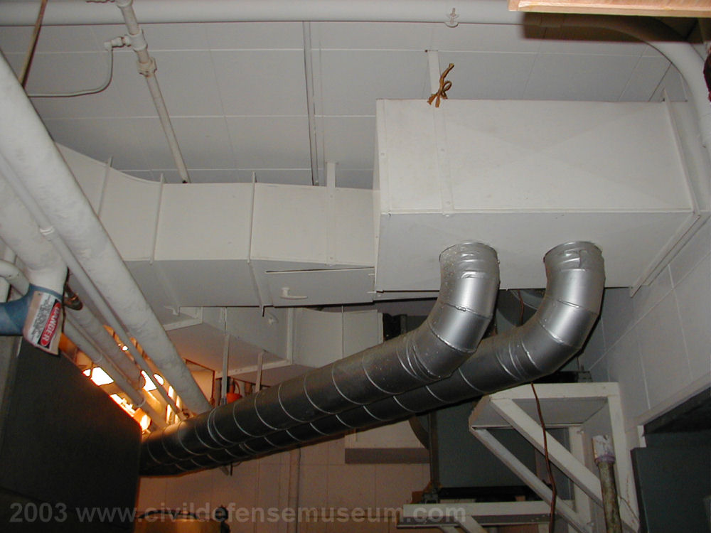
The above left photo - 20 shows the gas system blower (large gray fan housing at center right in photo) and it's inlet duct. Directly on the other side of the wall the blower is mounted to is where the gas - particulate filter chamber is located. The filter system blower in just up and to the right of the gas system blower.
The above right photo - 21 shows a bit of a different angle few from the same location where I took photo - 11. The Filter System blower still can't be seen very well from this angle either. The Filter System blower is up and behind the silver pipes which are the air intake pipes for the generators that used to be located in the mechanical room. The duct coming out of the wall over the doorway (gray doorway at bottom right which leads into the filter system room) is the same duct seen in photo - 10 above.
Exhaust Air Blower and Exhaust Anti-Blast Valve
 22 |
 23 |
The above left photo - 22 shows the air system exhaust blower. This blower is located in the men's restroom. Another photo of it can be seen on that page.
The above right photo - 23 shows the exhaust air anti-blast valve which is located in the corner of the courtyard area above the shelter kitchen.
How Did This System Operate? I have yet to find any documentation on this.....but I can speculate though.
The only information I can go with is what I have seen during my time looking the place over. Here are my ideas on how this system might have operated. I hope it's not too confusing.
I'll start with a list of the sections and components of the filter system. (see diagram at top of page or operation diagrams below for reference.)1. The Air Intake Anti-Blast Valve. (No filtering here only a overpressure protector.)
2. The Air Filter Chamber Itself. (Allows heavier particulates drawn into the system to settle there first.)
3. The Air Filter Bank. (These are the first air filters the air is drawn through. Actually two sets of filters.
The first set of filters appears to be standard fiberglass type air filters and the second set appear to be large pleated filters to catch small particulates.)
4. The Gas - Particulate Filter Section. (Small chamber containing two M14 filters. This chamber has a hatch with allows the G-P filters to be bypassed.)
5. The Air System Blower. (This blower draws outside air only through the Air Filter Bank while it is running.
This blower appears to have a fractional horsepower motor with a belt driven centrifugal fan.)
6. The Gas System Blower. (This blower draws air through the Gas - Particulate filters and the Air Filter Bank while it is running with the G-P Chamber access hatch closed,
or if the Gas Filter Chamber access hatch is opened it will bypass the Gas Particulate filters and draw air only though the air filter bank.
This blower is much larger than the Air System blower. It appears to have at least a 2hp motor which direct drives a centrifugal fan.)
7. The Air Conditioners (Just a mention here because they are part of the shelter air system.)
8. The Exhaust Air Blower. (Exhausts air from the shelter with no filtering that I can see.
This blower appears to slightly smaller than the Air System blower and also has a fractional horsepower motor with a belt driven centrifugal fan.)
9. The Exhaust Anti-Blast Valve. (No filtering here. Overpressure protector for exhaust system. Not shown on diagram above or below.)
I came up with the operation diagrams below to show how I think this system may have operated.
Schematic View Of Air Filter Bank Section Of System In Operation (Speculative)
Click Image To See Larger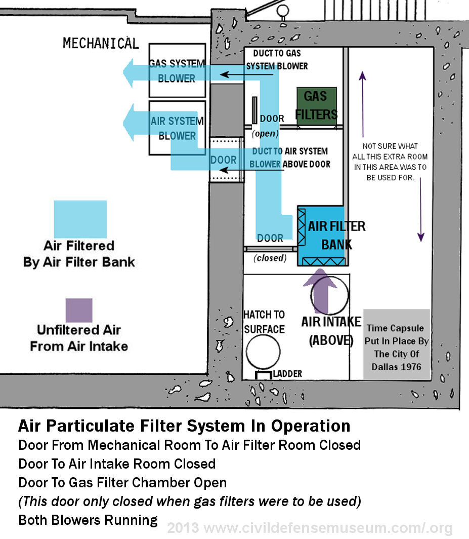
Here is what I have come up with regarding the operation of the Air Filter Bank section of the filtering system.
First, Here is my initial impression on how the system worked with only the Air Filter Bank in use.
1. With the Air System blower running, air is drawn in through the Intake Anti-blast Valve.
2. The air is then drawn through the Air Filter Bank (light blue).
3. The air is then blown through the Air System Blower, into the air conditioning unit,
through the air system of the shelter and finally out the Exhaust Air Blower and Exhaust Anti-blast Valve.
OR (New Information 2013)
During my July 2013 visit I noticed the note over the Gas - Particulate Chamber access door
that says "(handwritten) Keep Open Except (typed) Close This Door When Gas Filters Are To Be Used."
The note above the door leads me to believe that both blowers or maybe just the Gas System Blower would be running for ventilation.
NOTE: Maybe the Gas System Blower (since it's the larger or the two blowers) was the main blower and the Air System blower
was a back up blower.
Again all this is speculation. The large size of the Gas System blower would be necessary due
to, what must have been, a higher load on the air intake from the Gas - Particulate filters. Surely the G-P filters
would be a larger resistance to air flow than the Air Filter Bank. I guess all this could be calculated if
the capacity of the Gas System Blower was known. It does state 600 CFM (cubic feet per minute) on the G-P filters.(see next diagram below for Gas - Particulate Filters)
Using the Air System Blower and/or the Gas System blower then the flow would be.
1. With the Air System and/or Gas System blowers running, air is drawn in through the Intake Anti-blast Valve.
2. The air is then drawn through the Air Filter Bank (light blue).
3. The air is then blown through the Air System and/or Gas System blowers, into the air conditioning unit,
through the air system of the shelter and finally out the Exhause Air Blower and Exhaust Anti-blast Valve.
Schematic View Of Gas-Particulate Filter And Air Filter Bank Section Of System In Operation (Speculative)
Click Image To See Larger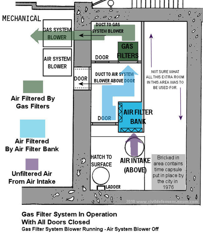
Here is what I have come up with regarding the operation of the Gas - Particulate Filter section of the filtering system.
As far as I can tell there is only one way for the Gas - Particulate Filter system to operate.
1. With only the Gas System Blower in operation the air is drawn through the Intake Anti-blast Valve.
2. The air is then drawn through the Air Filter Bank (light blue).
3. The air is then drawn through the Gas - Particulate filters (with G-P Filter Chamber access hatch closed.)
(Something else I don't know is if the two G-P Filters would be used together or one at a time.)
4. The air is then blown through the Gas System blower, into the air conditioning unit,
through the air system of the shelter and finally out the Exhause Air Blower and Exhaust Anti-blast Valve.
The Air System Blower outlet and the Gas System blower outlet are tied together and both run into the same air conditioning unit and into the shelter. The air is then exhausted out of the Exhaust Air Blower and out through the Exhaust Anti-blast Valve. I would like to go back and look this sytem over again. There must be a system of dampers in the ducting to close off the Air System Blower when only the Gas System Blower is operating or else the air would be driven back through the Air System Blower from the force of the Gas System blower running without the Air System Blower running.
More comments... Years ago I was able to take several tours of the what was originally the Office Of Civil Defense Region V Federal Underground Center. The OCD Region V center is now the FEMA Region VI center and is still in use. The OCD Region V center and the old Dallas Civil Defense EOC were built about the same time and have many similarities. The OCD Region V center has a very similar air filtering/ventilation system as the system seen here though the OCD/FEMA center system is much larger due to the larger size of the facility. That system is still used daily to provide fresh air to that underground center.
Go To The Rear/Outside Entry |
Go Back To The Mechanical Room |
Back to EOC Main |